
 |
Aux Princ : type
mémoire (aux/princ)
76543210 76543210 : bits (0 à 7)
X2103210 X1032103 : représentation des quadruplets en
mémoire
Aux Princ : type
mémoire (aux/princ)
76543210 76543210 : bits (0 à 7)
X...3210 X....... : représentation des quadruplets en
mémoire
Aux Princ : type
mémoire (aux/princ)
76543210 76543210 : bits (0 à 7)
X210.... X......3 : représentation des quadruplets en
mémoire
Aux Princ
Aux Princ
76543210 76543210 76543210 76543210 : bits (0 à 7)
X2103210 X1032103 X0321032 X3210321 : représentation de la
mémoire.
Aux Princ : type
mémoire (aux/princ)
76543210 76543210 : bits (0 à 7)
1CCC.... X......C : représentation des quadruplets en
mémoire
Aux Princ
Aux Princ : type
mémoire (aux/princ)
76543210 76543210 76543210 76543210 : bits de l'octet (0 à 7)
X2103210 X1032103 X0321032 X3210321 : représentation des
quadruplets en mémoire
0NNNNNNN 1CCCCCCN 1CCCCCCC 1CCCCCCC
1CCCCCCC 0NNNNNNC 1CCCCCNN 1CCCCCCC
1CCCCCCC 1CCCCCCC 0NNNNNCC 1CCCCNNN
1CCCCCCC 1CCCCCCC 1CCCCCCC 0NNNNCCC
 |
 |
 |
 |
 |
 |
 |
 |
 |
 |
Disk : Tests_DHGR.dsk
"-" files are DELETED files | "*" files are LOCKED files
----------------------------------------------------------------------
B A$2000 (008192) L$4000 (016384) 066 EXTASIE2
B A$2000 (008192) L$4000 (016384) 066 ELEPHANT2
B A$2000 (008192) L$4000 (016384) 066 BASTILLE2
B A$2000 (008192) L$4000 (016384) 066 TROMPE2
B A$2000 (008192) L$4000 (016384) 066 EQUIPE2
B A$2000 (008192) L$4000 (016384) 066 BRASIL2
B A$2000 (008192) L$4000 (016384) 066 PIERRE2
B A$2000 (008192) L$4000 (016384) 066 PORTRAIT2
This catalog contains 8 files. 0 were DELETED.
----------------------------------------------------------------------
 |
DOS 3.3 |
Download DHGR mode 3 graphics (gzipped) |
 |
Disk : Source_Decompacteur_Extasie.dsk
"-" files are DELETED files | "*" files are LOCKED files
----------------------------------------------------------------------
A A$0000 (000000) L$0092 (000146) 002 DISK*
T A$0000 (000000) L$1300 (004864) 019 T.DECOMP.EXTASIE.PRINC
B A$8000 (032768) L$023C (000572) 004 DECOMP.EXTASIE.PRINC
T A$0000 (000000) L$0900 (002304) 009 T.DISPLAY
B A$8000 (032768) L$0085 (000133) 002 DISPLAY
B A$8000 (032768) L$03C1 (000961) 005 DECOMP.EXTASIE.SCREEN
B A$2000 (008192) L$24B3 (009395) 038 CAMELOT.$F2
B A$4000 (016384) L$3FF8 (016376) 065 CAMELOT
This catalog contains 8 files. 0 were DELETED.
----------------------------------------------------------------------
 |
DOS 3.3 |
Download Extasie unpacker and viewer (gzipped) |
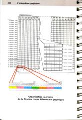
LIG COL
=== ===
---> partie correspondant à la mémoire AUX
000 00 ; 1ère colonne aux
001 00
002 00
...
189 00
190 00
191 00
000 01 ; 2nde colonne aux
001 01
002 01
...
189 01
190 01
191 01
000 02 ; 3ème colonne aux
001 02
002 02
...
189 02
190 02
191 02
etc...
000 39 ; dernière colonne aux
001 39
002 39
...
189 39
190 39
191 39
---> partie correspondant à la mémoire PRINC
000 00 ; 1ère colonne princ
001 00
002 00
...
189 00
190 00
191 00
000 01 ; 2nde colonne princ
001 01
002 01
...
189 01
190 01
191 01
etc...
000 39 ; dernière colonne princ
001 39
002 39
...
189 39
190 39
191 39
 |
 |
Apple II
Technical Notes
_____________________________________________________________________________
Developer Technical Support
Apple IIe
#3: Double High-Resolution Graphics
Revised by: Matt Deatherage, Glenn A. Baxter &
Cameron Birse November 1988
Written by: Peter
Baum
September 1983
This Technical Note is a tutorial on double high-resolution (hi-res)
graphics,
a feature available on 128K Apple IIe, IIc, and IIGS computers.
_____________________________________________________________________________
Introduction
This Note was originally written in the early days of double
high-resolution
graphics. At that time, there was no Apple IIc or IIGS,
therefore, some of
the things originally said may seem a little strange today, five years
later.
For example, this Note talks a fair amount about being sure that you
have a
Revision B Apple IIe with the jumper installed. All Apple IIe
computers
shipped since about mid-1983 have a Revision B motherboard, so this is
not
that big a concern anymore; furthermore, nearly every IIe out there has
the
aforementioned jumper already installed (it is not even an option on
some
third-party 80-column cards for the IIe).
Also, the IIc and IIGS are functionally equivalent (for the purposes of
this
article) to a Revision B IIe with the properly-jumpered 80-column card
installed, and most of the references made to the Apple IIe apply
equally to
the IIc and IIGS. We have tried to update most of the references
to avoid
confusion.
Considering the myriad of programming utilities, games, graphics
programs, and
other software that now uses double high-resolution graphics, it is
probable
that this Note will not be as vital as it once was. If you are
writing in
AppleSoft BASIC, you will probably find it easier to purchase a
commercial
double hi-res BASIC utility package to add double hi-res commands to
AppleSoft, rather than writing your own routines. Similarly,
those who want
double hi-res art will find a double hi-res art application much easier
than
trying to draw it from the monitor or machine language.
However, if you have the insatiable curiosity about these things that
Apple II
owners and developers so often are blessed (cursed?) with, this Note
will show
you how double high-resolution works, as well as giving a few
type-along
examples in the monitor to get your feet wet.
This article describes the double high-resolution display mode which is
available in the Apple IIc, IIGS, and the Apple IIe (with an extended
80-
column card). Double hi-res graphics provides twice the
horizontal resolution
and more colors than the standard high-resolution mode. On a
monochrome
monitor, double hi-res displays 560 horizontal by 192 vertical pixels,
while
on a color monitor, it allows the use of 16 colors.
Double High-Resolution on the Apple II Series
What is It?
The double high-resolution display mode that is available for the Apple
IIe
provides twice the horizontal resolution of the standard
high-resolution mode.
On a standard black-and-white video monitor, standard hi-res displays
280
columns and 192 rows of picture elements (pixels); the double hi-res
mode
displays 560 x 192 pixels. On a color monitor, the standard
hi-res mode
displays up to 140 columns of colors, each color being selected from
the group
of six colors available, with certain limitations. Double hi-res
displays 140
columns of color, for which all 16 of the low-resolution colors are
available.
Black/White Color
Standard 280 x 192 pixels 140
columns
Hi-Res
6 colors
Double 560 x 192 pixels
140 columns
Hi-Res
16 colors
Table 1-Comparison of
Standard and Double Hi-Res Graphics
How Do I Install It?
Installation of the double hi-res mode on your Apple IIe depends on the
following three conditions, discussed in detail below:
1. Presence of a Revision B motherboard
2. Installation of an extended 80-column text card
with jumper
3. A video monitor with a bandwidth of at least 14 MHz
First, your Apple IIe must have a Revision B (Rev-B) motherboard.
To find out
whether your computer's motherboard is a Rev-B, check the part number
on the
edge of the board nearest the back panel, above the slots. If the
board is a
Rev-B, the part number will be 820-0064-B. (Double hi-res does
not work on
systems containing a Rev-A motherboard.) If your computer's
motherboard is
not a Rev-B, and if you want to obtain one, contact your local Apple
dealer.
The second condition for installing double hi-res on your IIe is that
it must
have an extended 80-column text card installed. This card must be
installed
with a jumper connecting the two Molex-type pins on the board.
Warning: If your IIe has a Rev-A motherboard, do not
use an extended
80-column card with the jumper connection mentioned above;
the system will not work at all if you do.
The last requirement for operation in double hi-res mode is that your
video
monitor must have a bandwidth of at least 14 MHz. This bandwidth
is necessary
because a television set that requires a modulator will not reproduce
some
characters or graphic elements clearly, due to the high speed at which
the
computer sends out dots in this mode. Because most of the video
monitors
having a bandwidth of up to 14 MHz are black-and-white, the working
examples
in this article do not apply to color monitors. If you have a
video monitor,
please use it--instead of a television set--to display the following
examples.
The AppleColor composite monitors will work just fine.
Your Turn to be Creative (Volunteers, Anyone?)
The tutorial that occupies the rest of this Note assumes you are
working at
your Apple II as you read. The second part of the lesson
demonstrates the
double hi-res mode; therefore, before embarking on the second part, you
should
install a jumpered extended 80-column card in your Rev-B Apple IIe (or
use any
Apple IIc or IIGS).
Hands-On Practice with Standard Hi-Res
The Apple II hi-res graphics display is bit-mapped. In other
words, each dot
on the screen corresponds to a bit in the computer's memory. For
a real-life
example of bit-mapping, perform the following procedure, according to
the
instructions given below. (The symbol <cr> indicates a
carriage return.)
1. Boot the system.
2. Engage the Caps Lock key, and type
HGR<cr>. (This instruction
should clear the top of the screen.)
3. Type CALL -151 <cr>. (The system is
now in the monitor mode, and
the prompt should appear as an asterisk
(*).)
4. Type 2100:1 <cr>. One single dot
should appear in the upper left-
hand corner of the screen.
Congratulations! You have just plotted your first hi-res
pixel. (Not an
astonishing feat, but you have to start somewhere.)
With a black-and-white monitor, the bits in memory have a simple
correspondence with the dots (pixels) on the screen. A dot of
light appears
if the corresponding bit is set (has a value of 1), but remains
invisible if
the bit is off (has a value of zero). (The dot appears white on a
black-and-
white monitor, and green on a green-screen monitor, such as Apple's
Monitor
/// or Monitor II. For simplicity, we shall refer to an invisible
dot as a
black dot or pixel.) Two visible dots located next to each other
appear as a
single wide dot, and many adjacent dots appear as a line. To
obtain a display
of another dot and a line, follow the steps listed below:
1. Type 2080:40 <cr>. A dot should appear
above and to the right of
the dot you produced in the last
exercise.
2. Type 2180:7F <cr>. A small horizontal
line should appear below
the first dot you produced.
>From Bits and Bytes to Pixels
The seven low-order bits in each display byte control seven adjacent
dots in a
row. A group of 40 consecutive bytes in memory controls a row of
280 dots (7
dots per byte, multiplied by 40 bytes). In the screen display,
the least-
significant bit of each byte appears as the leftmost pixel in a group
of 7
pixels. The second least-significant bit corresponds to the pixel
directly to
the right of the pixel previously displayed, and so on. To watch
this
procedure in action, follow the steps listed below. The dots will
appear in
the middle of your screen.
1. Type 2028:1 <cr>.
2. Type 2828:2 <cr>.
3. Type 3028:4 <cr>.
The three bits you specified in this exercise correspond to three
pixels that
are displayed one after another, from left to right.
The most-significant bit in each byte does not correspond to a
pixel.
Instead, this bit is used to shift the positions of the other seven
bits in
the byte. For a demonstration of this feature, follow the steps
listed below:
1. Type 2050:8 <cr>.
2. Type 2850:8 <cr>.
3. Type 3050:8 <cr>.
You will notice that the dots align themselves vertically. Now do
the
following:
4. Type 2450:88 <cr>.
The new dot (that is, the one that corresponds to the bit you just
specified)
does not line up with the dots you displayed earlier. Instead, it
appears to
be shifted one "half-dot" to the right.
5. To demonstrate that this dot really is a new dot,
and not just the old
dot shifted by one dot position, type
2050:18 <cr>, 2850:18 <cr>.
You will notice that the dot mentioned under step 4 (the dot that was
not
aligned with the other seven dots) is straddled by the dots above and
below
it. (The use of magnifying lenses is permitted.)
Shifting the pixel one half-dot, by setting the high, most-significant
bit is
most often used for color displays. When the high bit of a byte
is set to
generate this shifted dot (which is also called the half-dot shift),
then all
the dots for that byte will be shifted one half dot. The half-dot
shift does
not exist in the double hi-res mode.
The Figure 1 shows the memory map for the standard hi-res graphics mode.
Horizontal Offset
Base | $00 | $01 | $02 |
$03 $24 | $25 | $26 |
$27 |
_____|_____|_____|_____|_____
_____|_____|_____|_____|
$2000|
| |
| |
| |
| | |
$2080|
| |
| |
| |
| | |
$2100|
| |
| |
| |
| | |
$2180|
| |
| |
| |
| | |
$2200|
| |
| |
| |
| | |
$2280|
| |
| |
| |
| | |
$2300|
| |
| |
| |
| | |
$2380|
| |
| |
| |
| | |
$2028|
| |
| \
\ | |
| |
$20A8|
| |
| \
\ | |
| |
$2128|
| |
| /
/ | |
| |
$21A8|
| |
| /
/ | |
| |
$2228|
| |
| /
/ |
| | |
$22A8|
| | |
/ /
| |
| |
$2328|
| | |
/ /
| |
| |
$23A8|
| | |
\ \
| |
| |
$2050|
| | |
\ \
| |
| |
$20D0|
| |
| |
| |
| | |
$2150|
| |
| |
| |
| | |
$21D0|
| |
| |
| |
| | |
$2250|
| |
| |
| |
| | |
$22D0|
| |
| |
| |
| | |
$2350|
| |
| |
| |
| | |
$23D0|
| |
| |
| |
| | |
Figure 1 - Standard Hi-Res Memory Map
Note: This memory map is in Chapter 2 of the Apple IIe Technical
Reference,
First Printing, January 1987.
Figure 2 shows the box subdivisions for the memory map in Figure 1.
Offset
Bit
from
LSB
base | 6 | 5 | 4 | 3 | 2 | 1 | 0 |
_______|___|___|___|___|___|___|___|
+$0000 | | | |
| | | |
+$0400 | | | |
| | | |
+$0800 | | | |
| | | |
+$0C00 | | | |
| | | |
+$1000 | | | |
| | | |
+$1400 | | | |
| | | |
+$1800 | | | |
| | | |
+$1C00 | | | |
| | | |
Figure 2 - Box Subdivisions
of the Standard Memory Map
Note: This figure is the inset of the hi-res graphics display map in
Chapter 2 of the Apple IIe Technical
Reference, First Printing, January 1987.
For example, the first memory address of each screen line for the first
few
lines is as follows:
$2000, $2400, $2800, $2C00, $3000, $3400, $3800, $3C00, $2080, $2480,
etc.
Each of the 24 boxes contains 8 screen lines for a total of 192
vertical lines
per screen. Each of the 40 boxes per line contains 7 pixels
for a total of
280 pixels horizontally across each line.
The Intricacies of Double Hi-Res
Because the double high-resolution graphics mode provides twice the
horizontal
dot density as standard hi-res graphics does, double hi-res requires
twice as
much memory as does standard hi-res. If you spent many hours
committing the
standard hi-res memory map to memory, don't despair; double hi-res
still uses
the hi-res graphics page (but only to represent half the picture, so to
speak). In the double hi-res mode, the hi-res graphics page is
compressed to
fit into half of the display. The other half of the display is
stored in
memory (called the auxiliary (aux) memory) on the extended 80-column
card.
(This article refers to the standard hi-res graphics page, which
resides in
main memory, as the motherboard (main) memory.)
The auxiliary memory uses the same addresses used by the standard
hi-res
graphics page (page 1, $2000 through $3FFF). The hi-res graphics
page stored
in auxiliary memory is known as hi-res page 1X. The graphics
pages in
auxiliary memory are bank-switched memory, which you can switch in by
activating some of the soft switches. (Adventurous readers may
want to skip
ahead to Using the Auxiliary Memory, which appears later in this Note.)
The memory mapping for the hi-res graphics display is analogous to the
technique used for the 80-column display. The double hi-res
display
interleaves bytes from the two different memory pages (auxiliary and
motherboard). Seven bits from a byte in the auxiliary memory bank
are
displayed first, followed by seven bits from the corresponding byte on
the
motherboard. The bits are shifted out the same way as in standard
hi-res
(least-significant bit first). In double hi-res, the most
significant bit of
each byte is ignored; thus, no half-dot shift can occur. (This
feature is
important, as you will see when we examine double hi-res in color.)
The memory map for double hi-res appears in Figure 3.
Horizontal Offset
$00 $01
$02 $03
$24 $25 $26 $27
M M
M
M
M M
M M
A a A a A
a A a A
a A a A a A a
|u i |u i |u i |u
i u i |u i
|u i |u i |
Base |x |n |x |n |x |n |x |n
x |n |x |n |x |n |x |n |
_____|__|__|__|__|__|__|__|__
__|__|__|__|__|__|__|__|
$2000| |
| |
| |
| |
| |
$2080| |
| |
| |
| |
| |
$2100| |
| |
| |
| |
| |
$2180| |
| |
| |
| |
| |
$2200| |
| |
| |
| |
| |
$2280| |
| |
| |
| |
| |
$2300| |
| |
| |
| |
| |
$2380| |
| |
| |
| |
| |
$2028| |
| |
\ \ |
| | |
$20A8| |
| |
\ \ |
| | |
$2128| |
| |
/ / |
| | |
$21A8| |
| |
/ / |
| | |
$2228| |
| |
/ /
| |
| |
$22A8| |
| | /
/ |
| | |
$2328| |
| | /
/ |
| | |
$23A8| |
| | \
\ |
| | |
$2050| |
| | \
\ |
| | |
$20D0| |
| |
| |
| |
| |
$2150| |
| |
| |
| |
| |
$21D0| |
| |
| |
| |
| |
$2250| |
| |
| |
| |
| |
$22D0| |
| |
| |
| |
| |
$2350| |
| |
| |
| |
| |
$23D0| |
| |
| |
| |
| |
Figure 3 - Double Hi-Res Memory Map
Note: This memory map is in Chapter 2 of the Apple IIe Technical
Reference,
First Printing, January 1987.
Each box is subdivided exactly the same way it is in the standard
hi-res mode.
Obtaining a Double-Hi-Res Display
To display the double hi-res mode, set the following soft switches:
In the monitor In AppleSoft
Read
PEEK
HI-RES
$C057
49239
GR
$C050
49232
AN3
$C05E
49246
MIXED
$C053
49235
In the monitor In AppleSoft
Write
POKE
80COL
$C00D
49165,0
Annunciator 3 (AN3) must be turned off to get into double hi-res
mode. You
turn it off by reading location 49246 ($C05E). Note that whenever
you press
Control-Reset, AN3 is turned on; therefore, each time you press
Control-Reset,
you must turn AN3 off again.
If you are using MIXED mode, then the bottom four lines on the screen
will
display text. If you have not turned on the 80-column card, then
every second
character in the bottom four lines of text will be a random
character. (The
reason is that although the hardware displays 80 columns of characters,
the
firmware only updates the 40-column screen, which consists of the
characters
in the odd-numbered columns. The characters in even-numbered
columns then
consist of random characters taken from text page 1X in the auxiliary
memory.)
To remove the even characters from the bottom four lines on the screen,
type
PR#3<CR> from AppleSoft (type 3^P in the monitor). This
procedure clears the
memory locations on page 1X.
Using the Auxiliary Memory
The auxiliary memory consists of several different sections, which you
can
select by using the soft switches listed below. A pair of memory
locations is
dedicated to each switch. (One location turns the switch on; the
other turns
it off.) You activate a switch by writing to the appropriate
memory location.
The write instruction itself is what activates the switch; therefore,
it does
not matter what data you write to the memory location. The soft
switches are
as follows:
In the monitor In AppleSoft
Write
POKE
80STORE off
$C000
49152,0
on
$C001
49153,0
RAMRD off
$C002
49154,0
on
$C003
49155,0
RAMWRT off
$C004
49156,0
on
$C005
49157,0
PAGE2 off
$C054
49236,0
on
$C055
49237,0
HIRES off
$C056
49238,0
on
$C057
49239,0
A routine called AUXMOVE ($C311), located in the 80-column firmware, is
also
very handy, as we will see below.
Accessing memory on the auxiliary card with the soft switches has the
following characteristics. Memory maps, which help clarify the
descriptions,
are in Figures 4, 5, and 6.
1. To activate the PAGE2 and HIRES switches, you need
only read
(PEEK) from the corresponding memory
locations (instead of writing
to them, as you do for the other three
switches).
2. The PAGE2 switch normally selects the display
page, in either
graphics or text mode, from either page
1 or page 2 of the
motherboard memory. However, it
does so only when the 80STORE
switch is off.
3. If the 80STORE switch is on, then the function of
the PAGE2 switch
changes. When 80STORE is on, then
PAGE2 switches in the text
page, locations $400-7FF, from auxiliary
memory (text page 1X),
instead of switching the display screen
to the alternate video
page (page 2 on the motherboard).
When 80STORE is on, the PAGE2
switch determines which memory bank
(auxiliary or motherboard) is
used during any access to addresses $400
through 7FF. When the
80STORE switch is on, it has priority
over all other switches.
4. If the 80STORE switch is on, then the PAGE2 switch
only switches
in the graphics page 1X from the
auxiliary memory if the HIRES
switch is also on. (Note that this
circumstance is slightly
different from that described in item
3.) When 80STORE is on, and
if the HIRES switch is also on, then the
PAGE2 switch selects the
memory bank (auxiliary or motherboard)
for accesses to a memory
location within the range $2000 through
3FFF. If the HIRES switch
is off, then any access to an memory
location within the range
$2000 through 3FFF uses the motherboard
memory, regardless of the
state of the PAGE2 switch.
5. If the 80STORE switch is off, and if the RAMRD and
RAMWRT switches
are on, then any reading from or writing
to address space $200-
$BFFF gains access to the auxiliary
memory. If only one of the
switches, RAMRD, for example, is set,
then only the appropriate
operation (in this case a read) will be
performed on the auxiliary
memory. If only RAMWRT is set,
then all write operations access
the auxiliary memory. When the
80STORE switch is on, it has
higher priority than the RAMRD and
RAMWRT switches.
Main
Memory
Auxiliary Memory
___________
_________________ ___________
$FFFF
|///////////|
| |
|///Bank////|
| Bank |
|/Switched//|
| Switched |
|//Memory///|
| Memory |
|///////////|
| |
|___________|___________ _____
|___________|___________
$DFFF |///////////|///////////|
|
| |
|//Bank 1///|//Bank
2///| | Bank 1
| Bank 2 |
$D000 |///////////|///////////|
|
| |
|___________|___________| _____
|___________|___________|
___________
_________________ ___________
$BFFF
|///////////|
| |
|///////////|
| |
|///////////|
| |
|///////////|
| |
|///////////|
| |
|___________| _________________
|___________|
$5FFF
|///////////|
| |
|//Hi-Res///|
| Hi-Res |
|/Graphics//|
| Graphics |
|//Page
2///|
| Page 2X |
$4000
|///////////|
| |
|___________| _________________
|___________|
$3FFF
|///////////|
| |
|//Hi-Res///|
| Hi-Res |
|/Graphics//|
| Graphics |
|//Page
1///|
| Page 1X |
$2000
|///////////|
| |
|___________| _________________
|___________|
|///////////|
| |
|///////////|
| |
|///////////|
| |
|___________| _________________
|___________|
$0BFF
|///////////|
| |
|///Text////|
| Text |
|//Page
2///|
| Page 2X |
$0800
|///////////|
| |
|___________| _________________
|___________|
$07FF
|///////////|
| |
|///Text////|
| Text |
|//Page
1///|
| Page 1X |
$0400
|///////////|
| |
|___________| _________________
|___________|
|///////////|
| |
|///////////|
| |
|///////////|
| |
|___________| _________________
|___________|
$01FF
|///////////|
| |
|/Stack
and/|
| Alternate |
|/Zero
Page/|
| Stack and |
|///////////|
| Zero Page |
$0000
|///////////|
| |
|___________| _________________
|___________|
__________________________ ______
| 80STORE | OFF | ON |
|//////|
|______________|_____|_____| |//////|
| PAGE2 | X | OFF
| |//////|
|______________|_____|_____| |______|
| HIRES | X
| X | Active
|______________|_____|_____| Memory
| RAMRD/RAMWRT | OFF | OFF |
|______________|_____|_____|
Figure 4A - Memory Map One-A
Main
Memory
Auxiliary Memory
___________
_________________ ___________
$FFFF
|///////////|
| |
|///Bank////|
| Bank |
|/Switched//|
| Switched |
|//Memory///|
| Memory |
|///////////|
| |
|___________|___________ _____
|___________|___________
$DFFF |///////////|///////////|
|
| |
|//Bank 1///|//Bank
2///| | Bank 1
| Bank 2 |
$D000 |///////////|///////////|
|
| |
|___________|___________| _____
|___________|___________|
___________
_________________ ___________
$BFFF |
|
|///////////|
|
|
|///////////|
|
|
|///////////|
|
|
|///////////|
|
|
|///////////|
|___________| _________________
|___________|
$5FFF |
|
|///////////|
| Hi-Res
|
|//Hi-Res///|
| Graphics
|
|/Graphics//|
| Page 2
|
|//Page 2X//|
$4000 |
|
|///////////|
|___________| _________________
|___________|
$3FFF |
|
|///////////|
| Hi-Res
|
|//Hi-Res///|
| Graphics
|
|/Graphics//|
| Page 1
|
|//Page 1X//|
$2000 |
|
|///////////|
|___________| _________________
|___________|
|
|
|///////////|
|
|
|///////////|
|
|
|///////////|
|___________| _________________
|___________|
$0BFF |
|
|///////////|
| Text
|
|///Text////|
| Page 2
|
|//Page 2X//|
$0800 |
|
|///////////|
|___________| _________________
|___________|
$07FF |
|
|///////////|
| Text
|
|///Text////|
| Page 1
|
|//Page 1X//|
$0400 |
|
|///////////|
|___________| _________________
|___________|
|
|
|///////////|
|
|
|///////////|
|
|
|///////////|
|___________| _________________
|___________|
$01FF
|///////////|
| |
|/Stack
and/|
| Alternate |
|/Zero
Page/|
| Stack and |
|///////////|
| Zero Page |
$0000
|///////////|
| |
|___________| _________________
|___________|
__________________________ ______
| 80STORE | OFF | ON |
|//////|
|______________|_____|_____| |//////|
| PAGE2 | X |
ON | |//////|
|______________|_____|_____| |______|
| HIRES | X
| X | Active
|______________|_____|_____| Memory
| RAMRD/RAMWRT | ON | ON |
|______________|_____|_____|
Figure 4B - Memory Map One-B
Main
Memory
Auxiliary Memory
___________
_________________ ___________
$FFFF
|///////////|
| |
|///Bank////|
| Bank |
|/Switched//|
| Switched |
|//Memory///|
| Memory |
|///////////|
| |
|___________|___________ _____
|___________|___________
$DFFF |///////////|///////////|
|
| |
|//Bank 1///|//Bank
2///| | Bank 1
| Bank 2 |
$D000 |///////////|///////////|
|
| |
|___________|___________| _____
|___________|___________|
___________
_________________ ___________
$BFFF
|///////////|
| |
|///////////|
| |
|///////////|
| |
|///////////|
| |
|///////////|
| |
|___________| _________________
|___________|
$5FFF
|///////////|
| |
|//Hi-Res///|
| Hi-Res |
|/Graphics//|
| Graphics |
|//Page
2///|
| Page 2X |
$4000
|///////////|
| |
|___________| _________________
|___________|
$3FFF
|///////////|
| |
|//Hi-Res///|
| Hi-Res |
|/Graphics//|
| Graphics |
|//Page
1///|
| Page 1X |
$2000
|///////////|
| |
|___________| _________________
|___________|
|///////////|
| |
|///////////|
| |
|///////////|
| |
|___________| _________________
|___________|
$0BFF
|///////////|
| |
|///Text////|
| Text |
|//Page
2///|
| Page 2X |
$0800
|///////////|
| |
|___________| _________________
|___________|
$07FF |
|
|///////////|
| Text
|
|///Text////|
| Page 1
|
|//Page 1X//|
$0400 |
|
|///////////|
|___________| _________________
|___________|
|///////////|
| |
|///////////|
| |
|///////////|
| |
|___________| _________________
|___________|
$01FF
|///////////|
| |
|/Stack
and/|
| Alternate |
|/Zero
Page/|
| Stack and |
|///////////|
| Zero Page |
$0000
|///////////|
| |
|___________| _________________
|___________|
__________________________ ______
| 80STORE | ON
| | |//////|
|______________|_____|_____| |//////|
| PAGE2 | ON
| | |//////|
|______________|_____|_____| |______|
| HIRES | OFF
| | Active
|______________|_____|_____| Memory
| RAMRD/RAMWRT | OFF | |
|______________|_____|_____|
Figure 5A - Memory Map Two-A
Main
Memory
Auxiliary Memory
___________
_________________ ___________
$FFFF
|///////////|
| |
|///Bank////|
| Bank |
|/Switched//|
| Switched |
|//Memory///|
| Memory |
|///////////|
| |
|___________|___________ _____
|___________|___________
$DFFF |///////////|///////////|
|
| |
|//Bank 1///|//Bank
2///| | Bank 1
| Bank 2 |
$D000 |///////////|///////////|
|
| |
|___________|___________| _____
|___________|___________|
___________
_________________ ___________
$BFFF
|///////////|
| |
|///////////|
| |
|///////////|
| |
|///////////|
| |
|///////////|
| |
|___________| _________________
|___________|
$5FFF
|///////////|
| |
|//Hi-Res///|
| Hi-Res |
|/Graphics//|
| Graphics |
|//Page
2///|
| Page 2X |
$4000
|///////////|
| |
|___________| _________________
|___________|
$3FFF |
|
|///////////|
| Hi-Res
|
|//Hi-Res///|
| Graphics
|
|/Graphics//|
| Page 1
|
|//Page 1X//|
$2000 |
|
|///////////|
|___________| _________________
|___________|
|///////////|
| |
|///////////|
| |
|///////////|
| |
|___________| _________________
|___________|
$0BFF
|///////////|
| |
|///Text////|
| Text |
|//Page
2///|
| Page 2X |
$0800
|///////////|
| |
|___________| _________________
|___________|
$07FF |
|
|///////////|
| Text
|
|///Text////|
| Page 1
|
|//Page 1X//|
$0400 |
|
|///////////|
|___________| _________________
|___________|
|///////////|
| |
|///////////|
| |
|///////////|
| |
|___________| _________________
|___________|
$01FF
|///////////|
| |
|/Stack
and/|
| Alternate |
|/Zero
Page/|
| Stack and |
|///////////|
| Zero Page |
$0000
|///////////|
| |
|___________| _________________
|___________|
__________________________ ______
| 80STORE | ON
| | |//////|
|______________|_____|_____| |//////|
| PAGE2 | ON
| | |//////|
|______________|_____|_____| |______|
| HIRES | ON
| | Active
|______________|_____|_____| Memory
| RAMRD/RAMWRT | OFF | |
|______________|_____|_____|
Figure 5B - Memory Map Two-B
Main
Memory
Auxiliary Memory
___________
_________________ ___________
$FFFF
|///////////|
| |
|///Bank////|
| Bank |
|/Switched//|
| Switched |
|//Memory///|
| Memory |
|///////////|
| |
|___________|___________ _____
|___________|___________
$DFFF |///////////|///////////|
|
| |
|//Bank 1///|//Bank
2///| | Bank 1
| Bank 2 |
$D000 |///////////|///////////|
|
| |
|___________|___________| _____
|___________|___________|
___________
_________________ ___________
$BFFF |
|
|///////////|
|
|
|///////////|
|
|
|///////////|
|
|
|///////////|
|
|
|///////////|
|___________| _________________
|___________|
$5FFF |
|
|///////////|
| Hi-Res
|
|//Hi-Res///|
| Graphics
|
|/Graphics//|
| Page 2
|
|//Page 2X//|
$4000 |
|
|///////////|
|___________| _________________
|___________|
$3FFF |
|
|///////////|
| Hi-Res
|
|//Hi-Res///|
| Graphics
|
|/Graphics//|
| Page 1
|
|//Page 1X//|
$2000 |
|
|///////////|
|___________| _________________
|___________|
|
|
|///////////|
|
|
|///////////|
|
|
|///////////|
|___________| _________________
|___________|
$0BFF |
|
|///////////|
| Text
|
|///Text////|
| Page 2
|
|//Page 2X//|
$0800 |
|
|///////////|
|___________| _________________
|___________|
$07FF
|///////////|
| |
|///Text////|
| Text |
|//Page
1///|
| Page 1X |
$0400
|///////////|
| |
|___________| _________________
|___________|
|
|
|///////////|
|
|
|///////////|
|
|
|///////////|
|___________| _________________
|___________|
$01FF
|///////////|
| |
|/Stack
and/|
| Alternate |
|/Zero
Page/|
| Stack and |
|///////////|
| Zero Page |
$0000
|///////////|
| |
|___________| _________________
|___________|
__________________________ ______
| 80STORE | ON
| | |//////|
|______________|_____|_____| |//////|
| PAGE2 | OFF
| | |//////|
|______________|_____|_____| |______|
| HIRES | OFF
| | Active
|______________|_____|_____| Memory
| RAMRD/RAMWRT | ON | |
|______________|_____|_____|
Figure 6A - Memory Map Three-A
Main
Memory
Auxiliary Memory
___________
_________________ ___________
$FFFF
|///////////|
| |
|///Bank////|
| Bank |
|/Switched//|
| Switched |
|//Memory///|
| Memory |
|///////////|
| |
|___________|___________ _____
|___________|___________
$DFFF |///////////|///////////|
|
| |
|//Bank 1///|//Bank
2///| | Bank 1
| Bank 2 |
$D000 |///////////|///////////|
|
| |
|___________|___________| _____
|___________|___________|
___________
_________________ ___________
$BFFF |
|
|///////////|
|
|
|///////////|
|
|
|///////////|
|
|
|///////////|
|
|
|///////////|
|___________| _________________
|___________|
$5FFF |
|
|///////////|
| Hi-Res
|
|//Hi-Res///|
| Graphics
|
|/Graphics//|
| Page 2
|
|//Page 2X//|
$4000 |
|
|///////////|
|___________| _________________
|___________|
$3FFF
|///////////|
| |
|//Hi-Res///|
| Hi-Res |
|/Graphics//|
| Graphics |
|//Page
1///|
| Page 1X |
$2000
|///////////|
| |
|___________| _________________
|___________|
|
|
|///////////|
|
|
|///////////|
|
|
|///////////|
|___________| _________________
|___________|
$0BFF |
|
|///////////|
| Text
|
|///Text////|
| Page 2
|
|//Page 2X//|
$0800 |
|
|///////////|
|___________| _________________
|___________|
$07FF
|///////////|
| |
|///Text////|
| Text |
|//Page
1///|
| Page 1X |
$0400
|///////////|
| |
|___________| _________________
|___________|
|
|
|///////////|
|
|
|///////////|
|
|
|///////////|
|___________| _________________
|___________|
$01FF
|///////////|
| |
|/Stack
and/|
| Alternate |
|/Zero
Page/|
| Stack and |
|///////////|
| Zero Page |
$0000
|///////////|
| |
|___________| _________________
|___________|
__________________________ ______
| 80STORE | ON
| | |//////|
|______________|_____|_____| |//////|
| PAGE2 | OFF
| | |//////|
|______________|_____|_____| |______|
| HIRES | ON
| | Active
|______________|_____|_____| Memory
| RAMRD/RAMWRT | ON | |
|______________|_____|_____|
Figure 6B - Memory Map Three-B
Shortcuts: Writing to Auxiliary Memory from the Keyboard
Press Control-Reset, then type CALL -151 <cr> (to enter the
monitor). Now
type the following hexadecimal addresses to turn on the double hi-res
mode:
C057 (for hi-res)
C050 (for
graphics)
C053 (for mixed
mode)
C05E Turns off
AN3 for double hi-res
C00D:0 Turns on the 80COL
switch
This procedure usually causes the display of a random dot pattern at
the top
of the screen, while the bottom four lines on the screen contain
text. To
clear the screen, follow the steps listed below:
1. Type 3D0G <cr> to return to BASIC.
2. Type HGR <cr> to clear half of the
screen. (The characters you
type will probably appear in alternating
columns. This is not a
cause for alarm; as noted above, the
firmware simply thinks you
are working with a 40-column
display.) Remember that hi-res
graphics commands do not know about the
half of the screen stored
on page 1X in the auxiliary
memory. Therefore, only page 1 (that
is, the first half) of the graphics page
on the motherboard is
cleared. As a result, in the the
screen display, only alternate
7-bit columns appear cleared.
On the other hand, if all of the screen
columns were cleared after
the HGR command, then chances are good
that you are not in double
hi-res mode. If your screen was
cleared then to determine which
mode you are in, type the following
instructions:
CALL -151
2000:FF
2001<2000.2027M
If a solid line appears across the top
of the screen, you are not
in double hi-res mode. (The line
that appears should be a dashed
or intermittent line: - - - - -
across the screen.) If you are
not in double hi-res mode, then make
sure that you do have a Rev.
B motherboard, and that the two
Molex-type pins on the extended
80-column card are shorted together with
the jumper block. Then
re-enter the instructions listed above.
If you are staring at a half-cleared screen, you can clear the
non-blank
columns by writing zeros to addresses $2000 through $3FFF on graphics
page 1X
of auxiliary memory. To do so, simply turn on the 80STORE switch,
turn on the
PAGE2 switch, then write to locations $2000, $2001, $2002, and so on up
through $3FFF. However, this procedure will not work if you try
it from the
monitor. The reason is that each time you invoke a monitor
routine, the
routine sets the PAGE2 switch back to page 1 so that it can display the
most
recent command that you entered. When you try to write to $2000,
etc. on the
auxiliary card, instead it will write to the motherboard memory.
Another way to obtain the desired result is to use the monitor's USER
command,
which forces a jump to memory location $3F8. You can place a JMP
instruction
starting at this memory location, so the program will jump to a routine
that
writes into hi-res page 1X. Fortunately, the system already
contains such a
routine: AUXMOVE.
Using AUXMOVE
You use the AUXMOVE routine to move data blocks between main and
auxiliary
memory, but the task still remains of setting up the routine so that it
knows
which data to write, and where to write it. To use this routine,
some byte
pairs in the zero page must be setup with the data block addresses, and
the
carry bit must be fixed to indicate the direction of the move.
You may not be
surprised to learn that the byte pairs in the zero page used by AUXMOVE
are
also the scratch-pad registers used by the monitor during instruction
execution. The result is that while you type the addresses for
the monitor's
move command, those addresses are being stored in the byte pairs used
by
AUXMOVE. Thereafter, you can call the AUXMOVE command directly,
using the
USER (Control-Y) command.
In practice, then, enter the following instructions:
C00A:0
(turns on the 80-column ROM, which
contains the AUXMOVE routine)
C000:0
(reason explained below)
3F8: 4C 11
C3 (the jump to AUXMOVE)
2000<2000.3FFF ^Y (where
^Y indicates that you should type
Control-Y)
The syntax for this USER (Control-Y) command is:
{AUXdest}<{MBstart}.{MBend}^Y
The command copies the values in the range MBstart to MBend in the
motherboard
memory into the auxiliary memory beginning at AUXdest. This
command is
analogous to the MOVE command.
You can use this procedure to transfer any block of data from the
motherboard
memory to hi-res page 1X. Working directly from the keyboard, you
can use a
data block transferred this way to fill in any part of a double hi-res
screen
image. The image to be stored in hi-res page 1X (i.e., the image
that will be
displayed in the even-numbered columns of the double hi-res picture)
must
first be stored in the motherboard memory. You can then use the
Control-Y
command to transfer the image to hi-res page 1X.
The AUXMOVE routine uses the RAMRD and RAMWRT switches to transfer the
data
blocks. Because the 80STORE switch overrides the RAMRD and RAMWRT
switches,
the 80STORE switch must be turned off--otherwise it would keep the
transfer
from occurring properly (hence the write to $C000 above).
If the 80STORE and HIRES switches are on and PAGE2 is off, when you
execute
AUXMOVE, any access to an address located within the range from $2000
to $3FFF
inclusive would use the motherboard memory, regardless of how RAMRD and
RAMWRT
are set. Entering the command C000:0 <cr> turns off
80STORE, thus letting the
RAMRD and RAMWRT switches control the memory banking.
The Control-Y trick described above only works for transferring data
blocks
from the main (motherboard) memory to auxiliary memory (because the
monitor
always enters the AUXMOVE routine with the carry bit set). To
move data
blocks from the auxiliary memory to the main memory, you must enter
AUXMOVE
with the carry bit clear. You can use the following routine to
transfer data
blocks in either direction:
301:AD 0 3
(loads the contents of address $300 into the
accumulator)
304:2A (rotates
the most-significant bit into the carry
flag)
305:4C 11 C3 (jump to $C311
(AUXMOVE))
3F8:4C 1 3 (sets
the Control-Y command to jump to address
$301)
Before using this routine, you must modify memory location $300,
depending on
the direction in which you want to transfer the data blocks. If
the transfer
is from the auxiliary memory to the motherboard, you must clear
location $300
to zero. If the transfer is from the motherboard to the auxiliary
memory, you
must set location $300 to $FF.
Two Double Hi-Res Pages
So far, we have only discussed using graphics pages 1 and 1X to display
double
hi-res pictures. But--analogous to the standard hi-res pages 1
and 2--two
double hi-res pages exist: pages 1 and 1X, at locations $2000
through 3FFF,
and pages 2 and 2X, at locations $4000 through 5FFF. The only
trick in
displaying the second double hi-res page is that you must turn off the
80STORE
switch. If the 80STORE switch is on, then only the first page (1
and 1X) is
displayed. Go ahead and try it:
C000:0 to turn off the
80STORE switch
C055 to turn on
the PAGE2 switch
The screen will fill with another display of random bits. Clear
the screen
using the instructions listed above (in the Using AUXMOVE section
). However,
this time, use addresses $4000 through 5FFF instead. (Don't be
alarmed by the
fact that the figures you are typing are not displayed on the
screen. They
are being "displayed" on text page 1.)
4000:0
4001<4000.5FFFM
4000<4000.5FFF ^Y
You will be delighted to learn that you can also use this trick to
display two
80-column text screens. The only problem here is that the
80-column firmware
continually turns on the 80STORE switch, which prevents the display of
the
second 80-column screen. However, if you write your own 80-column
display
driver, then you can use both of the 80-column screens.
Color Madness
It should come as no surprise that color-display techniques in double
hires
are different from color-display techniques in standard hi-res.
This
difference is because the half-dot shift does not exist in double
hi-res mode.
Instead of going into a dissertation on how a television set decodes
and
displays a color signal, I'll simply explain how to generate color in
double
hi-res mode. In the following examples, the term color monitor
refers to
either an NTSC monitor or a color television set. Both work;
however, the
displays will be much harder to see on the color television. The
generation
of color in double hi-res demands sacrifices. A 560 x 192 dot
display is not
possible in color. Instead, the horizontal resolution decreases
by a factor
of four (140 dots across the screen). Just as with a
black-and-white monitor,
a simple correspondence exists between memory and the pixels on the
screen.
The difference is that four bits are required to determine each color
pixel.
These four bits represent 16 different combinations: one for each
of the
colors available in double hi-res. (These are the same colors
that are
available in the low-resolution mode.)
Let's start by exploring the pattern that must be stored in memory to
draw a
single colored line across the screen. Use a color demonstration
program
(such as COLOR.TEST from older DOS 3.3 System Master disks) to adjust
the
colors displayed by your monitor. After you have adjusted the
colors, exit
from the color demonstration program.
The instructions that appear below are divided into groups separated by
blank
lines. Because it is very difficult (and, on a television set,
almost
impossible) to read the characters you are typing as they appear on the
screen, you will probably make typing errors. If the instructions
appear not
to work, then start again from the beginning of a group of instructions.
CALL
-151 (to
get into the monitor routine/program)
C050
(This set of instructions puts the computer
CO57
into double hi-res model.
C05E
C00D:0
2000:0
(This set of instructions clears first one half
2001<2000.3FFFM of
the screen, and then the other half of
3F8: 4C 11
C3 the screen.)
2000<2000.3FFF^Y
2100:11
4 (Two red
dots appear on top left of
screen)
2102<2100.2126M (A
dashed red line appears across screen)
2150:8
22 (Two
green dots appear near bottom left)
2152<2150.2175M
(Dashed green line appears across screen)
2100<2150.2177^Y (Fills
in the red line)
In contrast to conditions in standard hi-res, no half-dot shift occurs,
and
the most-significant bit of each byte is not used.
As noted above, four bits determine a color. You can paint a
one-color line
across the screen simply by repeating a four-bit pattern across the
screen,
but it is much easier to write a whole byte rather than just change
four bits
at a time. Since only seven bits of each byte are displayed (as
noted earlier
in our discussion of black-and-white double hi-res) and the pattern is
four
bits wide, it repeats itself every 28 bits or four bytes. Use the
instructions listed below to draw a line of any color across the screen
by
repeating a four byte pattern for the color as shown in Table 2.
2200: main1 main2 (Colored dots
appear at the left edge)
2202<2200.2226M (A
dashed, colored line appears)
2250: aux1 aux2
2250<2250.2276M
2200<2250.2276^Y (Fills
in line, using the selected color)
Repeated
Binary
Color aux1 main1
aux2 main2 Pattern
Black
00 00 00
00 0000
Magenta 08
11 22 44 0001
Brown
44 08 11
22 0010
Orange
4C 19 33
66 0011
Dark
Green 22 44
08 11 0100
Grey1
2A 55 2A
55 0101
Green
66 4C 19
33 0110
Yellow
6E 5D 3B
77 0111
Dark
Blue 11
22 44 08 1000
Violet
19 33 66
4C 1001
Grey2
55 2A 55
2A 1010
Pink
5D 3B 77
6E 1011
Medium
Blue 33 66
4C 19 1100
Light
Blue 3B 77
6E 5D 1101
Aqua
77 6E 5D
3B 1110
White
7F 7F 7F
7F 1111
Table 2-The Sixteen Colors
In Table 2, the heading aux1 indicates the first, fifth, ninth,
thirteenth,
etc. byte of each line (i.e., every fourth byte, starting with the
first
byte). The heading main1 indicates the second, sixth, tenth,
fourteenth, etc.
byte of each line (i.e., every fourth byte, starting with the second
byte).
The aux2 and main2 headings indicate every fourth byte, starting with
the
third and fourth bytes of each line, respectively. Aux1 and aux2
are always
stored in auxiliary memory, while main1 and main2 are always stored in
the
motherboard memory.
As you will infer from Table 2, the absolute position of a byte also
determines the color displayed. If you write an 8 into the first
byte at the
far left side of the screen (i.e., in the aux1 column), then a red dot
is
displayed. But if you write an 8 into the third byte at the left
side of the
screen (the aux2 column), then a dark green dot is displayed.
Remember, the
color monitor decides which color to display based on the relative
position of
the bits on each line (i.e., on how far the bits are from the left edge
of the
screen).
So far, so good. But suppose you want to display more than one
color on a
single line. It's easy: just change the four-bit pattern
that is stored in
memory. For example, if you want the left half of the line to be
red, and the
right half to be purple, then store the red pattern (8, 11, 22, 44) in
the
first 40 bytes of the line, then store the purple pattern (19, 33, 66,
4C) in
the second 40 bytes of the line. Table 2 is a useful reference
tool for
switching from one color to another, provided you make the change on a
byte
boundary. In other words, you must start a new color at the same
point in the
pattern at which the old color ended. For example, if the old
color stops
after you write a byte from the main1 column, then you should start the
new
color by storing the next byte in memory with a byte from the aux2
column.
This procedure is illustrated below:
2028:11 44 11 44 11 44 11 77 5D 77 5D 77 5D (creates
a dashed line
2128: 8 22 8 22 8 22 8 22 6E 3B 6E 3B
6E that is red then yellow)
2028<2128.2134^Y
(fills in the rest of
the colors)
Switching Colors in Mid-Byte
If you want a line to change color in the middle of a byte, you will
have to
recalculate the column, based on the information in Table 2.
Suppose you want
to divide the screen into three vertical sections, each a different
color.
The leftmost third of the screen ends in the middle of the 27th
character from
the left edge-that is, in an aux2 column of the color table.
(Dividing 27 by
4 gives a remainder of 3, which indicates the third column, or
aux2.) Your
pattern should change from the first color to the second color after
the 5th
bit of the 27th byte. You can change the color in the middle of a
byte by
selecting the appropriate bytes from the aux2 column of Table 2 and
concatenating two bits for the second color with five bits for the
first
color.
However, because the bits from each byte are shifted out in order from
least
significant to most significant, the two most significant bits (in this
case
bits 5 and 6, because bit 7 is unused) for the second color are
concatenated
with the five least significant bits for the first color. For
instance, if
you want the color to change from orange (the first color) to green
(the
second color), then you must append the two most significant bits (5
and 6) of
green to the five least significant bits (0-4) of orange. In
Table 2, the
aux2 column byte for green is 19, and the two most significant bits are
both
clear. The aux2 column byte for orange is 33, and the five least
significant
bits are equal to 10011. The new byte calculated from appending
green (00) to
orange (10011) yields 13 (0010011). Therefore, the first 26 bytes
of the line
come from the table values for orange; the 27th byte is 13, and the
next 26
bytes come from the table values for green.
2300: 19
66
(puts an orange line on the
screen)
2302<2300.2310M
2350: 4C 33
2352<2350.2360M
2300<2350.2360^Y
230D: 33 4C 33 4C 33 4C 33
4C (puts a green line next to it)
235D: 13 66 19 66 19 66 19
66 (note the first byte)
230D<235D.2363^Y
There you have it: a basic explanation of how double hi-res
works--except for
one or two anomalies. The first anomaly is that NTSC monitors
have a limited
display range. The second anomaly shows one of the features of
double hi-res
versus a limitation of standard hi-res.
An NTSC color monitor decides what color to display based on its view
of four
bit windows in each line, starting from the left edge of the
screen. The
monitor looks at the first four bits, determines which color is called
for,
then shifts one bit to the right and determines the color for this new
four-
bit window. But remember, the color depends not only on the
pattern, but also
the position of the pattern. To compensate for relative position
from the
left edge of the screen, the monitor keeps track of where on each line
each of
these windows start. (For those of you of the technical
persuasion, this is
done through the use of the color burst signal, which is a 3.58 MHz.
clock).
Try this example:
2000:0
Clears the screen
2001<2000.3FFFM
2000<2000.3FFF^Y
2001:66
Draws an orange box in the upper left
2401:66
2801:66
2C01:66
3001:66
2050:33
Draws a blue box below and to the right
3402<2050.2050^Y of the
orange box
3802<2050.2050^Y
3C02<2050.2050^Y
Notice that if the blue box was drawn at the top of the screen, next to
the
orange box, they would overlap. Yet, the boxes were drawn on two
different
columns, orange on main2 and blue on aux1. This can be explained
by the
previous paragraph, and the sliding windows. The monitor will
detect the
pattern for orange slightly after the main2 column, while the pattern
for blue
shows up before column aux1.
The orange pattern is as follows:
0000000 | 0110011 |0000000
look at four-bit windows and you will see
aux2 | main2
| aux1 an orange pattern overlaps on both
sides
If a pattern is repeated on a line, this overlap does not cause a
problem,
since the same color just overlaps itself. But watch what happens
when a new
pattern is started next to a different pattern:
3002<2050.2050^Y Puts a
blue pattern next to the orange one
2C02<2050.2050^Y
2802<2050.2050^Y
Where the blue overlaps the orange, you will see a white dot.
This effect is
because one of the four-bit windows the monitor sees is all 1s.
If two colors
are placed right next to each other, the monitor will sometimes display
a
third color, or fringe, at the boundary. This fringe effect is
especially
noticeable when there are a lot of narrow columns of different colors
next to
each other. (Next time you run COLOR TEST take a look at the
boundaries
between the colors).
The orange and blue patter is as follows:
0000000 |0110011 | 11001100
note the four 1s in a row at the boundary
aux2 | main2
| aux1 between orange and blue
Conclusion
Now you have the tools and the rules to the double hi-res mode.
As you can
see, double hi-res has more color with higher resolution than standard
hi-res.
You can even develop games that do fancy animation or scroll orange
objects
across green backgrounds. You can develop word processing
programs which use
different fonts or proportional character sets in black and
white. Have fun
playing with his new mode.
Further Reference
o Apple IIe Technical Reference
Manual
o Apple IIc Technical Reference
Manual, Second Edition
o Apple IIGS Hardware Reference
---------------------------------------------------------------
 |
 |
 |
 |
 |
 |
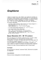 |
 |
 |
Groupes de discussion : comp.sys.apple2,
comp.emulators.apple2
De : "Arkain"
Date : Wed, 6 Sep 2000 17:05:33 -0500
Local : Mer 6 sep 2000 23:05
Objet : DHGR Video Riddle Solved!!!
A while back I set out to create a IIe emulator that could properly
handle
all of the features of the IIe, including the ones that were not
properly
documented. Some of those features included the DOUBLE HIRES display
mode(s). Most of you were under the impression that the system only
carried
1 DHGR mode that was 140x192x16 on a color monitor and 560x192x2 on a
monochrome monitor. I was under the impression that there were 3
distinct
modes always available, the 2 modes listed above and a third that mixes
the
2 above.
As it turned out... I was right... to a point. The reason that the modes
were clearly visible to me and not to the vast majority of you was that
I
had an Extended 80 Column AppleColor Card with an AppleColor RGB
monitor.
That setup provided graphics that were free of the color-bleeding that
comes
with composite displays.
While my old system is long-since gone, I have acquired a new one and
tested
various programs on it. This is the how and why of the DHGR video
display
(as best as I can figure).
There are indeed 3 modes of display for the DHGR graphics. Mode 1 is
560x192
monochrome, but due to the composite display system and the fact that
the
color signal is actually on in this mode, each dot on the screen
experiences
color bleeding similar to that of the HIRES display and precisely
identical
to the color bleeding that occurs on the 4 lines of 80 column text
below a
HIRES mixed-mode display. Why the color signal is on in this mode is
still a
mystery to me. I will do some more experimenting to determine the exact
nature of this. To properly set up this mode, run this code:
STA $CO52
;Full Screen
STA $C057
;HIRES
STA $C050
;Graphics
STA $C00C
;80 Columns OFF
STA $C05E
;AN3 OFF
STA $C05F
;AN3 ON
STA $C05E
;AN3 OFF
STA $C05F
;AN3 ON
STA $C00D
;80 Columns ON
STA $C05E
;AN3 OFF
-------
Mode 2 is 140x192 16 color. This is the mode most commonly associated
with
DHGR. It is already well documented. To properly set up this mode, run
this
code:
STA $CO52
;Full Screen
STA $C057
;HIRES
STA $C050
;Graphics
STA $C00C
;80 Columns OFF
STA $C05E
;AN3 OFF
STA $C05F
;AN3 ON
STA $C05E
;AN3 OFF
STA $C05F
;AN3 ON
STA $C00D
;80 Columns ON
STA $C05E
;AN3 OFF
STA $C05F
;AN3 ON
STA $C05E
;AN3 OFF
STA $C05F
;AN3 ON
STA $C05E
;AN3 OFF
-------
Mode 3 is a mix of modes 1 & 2. The last time I mentioned this
mode, someone
asked me how the system would know when to display dots and when to
display
colored blocks. The answer is that if bit 7 of a byte is set then the
contents of that byte are displayed in mode 1. I havent figured out
what the
effect is on surrounding color blocks that use bits from that byte yet,
but
I will. To properly set up this mode, run this code:
STA $CO52
;Full Screen
STA $C057
;HIRES
STA $C050
;Graphics
STA $C00C
;80 Columns OFF
STA $C05E
;AN3 OFF
STA $C05F
;AN3 ON
STA $C05E
;AN3 OFF
STA $C05F
;AN3 ON
STA $C00D
;80 Columns ON
STA $C05E
;AN3 OFF
STA $C05F
;AN3 ON
STA $C05E
;AN3 OFF
-------
Note that to get to B & W mode you just turn off AN3 after truning
on 80
columns; to get to mixed you toggle the switch an extra time; to get to
full
color mode you toggle the switch once more. Why modes 2 & 3 were
numbered
backwards is beyond me.
AN3 also has a peculiar effect on other graphic modes. In LORES mode,
AN3
causes the display to double the same way that it does in hires mode if
80COL is on. In HIRES mode, if 80COL is off AN3 causes a polarity shift
that
reverses the normal effect of the high bit.
I would appreciate it if someone else would take a little time to
verify
these findings. I know that these aren't the effect of the Extended 80
Column AppleColor card & monitor since I no-longer have those
devices.
BTW, does anyone know where I can find an RGB card & monitor for
the IIe? I
miss the crisp display!
Groupes de discussion : comp.sys.apple2.programmer
De : "Teodor Angelov"
Date : Mon, 23 Apr 2001 20:26:26 +0300
Local : Lun 23 avr 2001 18:26
Objet : Double Hires BW/Color mix?
Hello all,
Somebody has emailed me some information but I lost my hard drive and
the
message.
There is a special sequence of softswich calls ($C057/$C0XX...) which
enable
enhanced color modes in double hi-res - bit 7 is used to determine when
the
pixel group is displayed in color or B/W.
Can somebody send me this information?
Thanks in advance!
Teodor
P.S.: Please send reply (or cc) by email
Groupes de discussion : comp.sys.apple2.programmer
De : Jeff Blakeney
Date : Tue, 24 Apr 2001 19:33:07 GMT
Local : Mar 24 avr 2001 20:33
Objet : Re: Double Hires BW/Color mix?
I remember a conversation about this in comp.emulators.apple2 and if I
remember correctly, the conclusion was reached that this mixed
b&w/colour mode was a feature of the RGB card that the individual
who
brought it up was using in his machine.
It is definitely not a standard feature of any model of Apple II.
--
Jeff Blakeney - Dean of the Apple II Unversity on A2Central.com
1
2
ORG $8000
3
4 ********************************
5
*
*
6 * Décompresse en mémoire
une *
7 * image au format Extasie $F2 *
8 * (c)1986 Serge Hervy/Crealude *
9 * (p)atched 2006 by Deckard *
10
*
*
11 ********************************
12
13 * L'image compressée doit etre chargée en
$0900.
14 * Appel de ce programme pour décompresser.
15 * Après la décompression, on a:
16 * princ: $4000-$5FFF (zone normalement en ram aux)
17 * princ: $6000-$7FFF (zone normalement en ram princ)
18 * Il suffit ensuite de sauver l'image (format Dazzle
Draw)
19 * avec BSAVE MONIMAGE, A$4000, L$3FF8 (ou L$4000)
20
21 ********************************
22
23 ADR_IMG
EQU $0900 : stockage image
compressée
24
25 PTR_IMG_DCOMP EQU
$06 ; pointeur pour image
décompressée
26 PTR_IMG_COMP EQU
$08 ; pointeur sur image
compressée
27 PTR_IMG_COMP1 EQU
$18 ; pointeur sur image
compressée+1
28
29 ********************************
30
8000: A2 00
31
LDX #<ADR_IMG
8002: A0 09
32
LDY #>ADR_IMG
33
34 ********************************
35
36 * Pour utiliser le décompacteur, faire:
37 *
38
*
LDX #<ADR IMAGE COMPRESSEE
39
*
LDY #>ADR IMAGE COMPRESSEE
40
*
JSR EXTASIE
41
42 * On commence par la partie AUX.
43 * L'écriture se fait de la gauche vers la droite.
44 * On traite les colonnes de haut en bas.
45
46
8004: 84 09 47
EXTASIE STY
PTR_IMG_COMP+1 ; high
8006: 84 19
48
STY PTR_IMG_COMP1+1
8008: E8
49
INX
; saute 2 octets inutilisés
8009: E8
50
INX
800A: 86 08
51
STX PTR_IMG_COMP ; low
800C: E8
52
INX
800D: 86 18
53
STX PTR_IMG_COMP1
54
800F: 20 AE 80
55
JSR READY ; initialisations
8012: A9 01
56
LDA #1 ;
commence par partie AUX
8014: 8D B7 80
57
STA PRINCORAUX
8017: 20 24 80
58
JSR DECOMP
59
801A: 20 AE 80
60
JSR READY ; initialisations
801D: 8D B7 80
61
STA PRINCORAUX ; puis fait partie PRINC
(acc=0)
8020: 20 24 80
62
JSR DECOMP
8023: 60
63
RTS
64
65 *-------------------------------
66
8024: A0 00 67
DECOMP LDY
#0 ; récupère
octet position
pointée courante
8026: B1 08
68
LDA (PTR_IMG_COMP),Y
8028: 8D BA 80
69
STA REPETITION
802B: 30 18
70
BMI :2 ;
bit 7 = 1 -> valeur
répétée
71
72 * Traite un certain nombre d'octets non
répétés
73
802D: A0 00 74
:1
LDY #0 ;
commence à l'octet
suivant
802F: B1 18
75
LDA (PTR_IMG_COMP1),Y
8031: 20 7B 80
76
JSR WT_IMG_DCOMP
8034: 20 6B 80
77
JSR NEXT_POS ; positionne pour prochain
octet
8037: CE BA 80
78
DEC REPETITION
803A: D0 F1
79
BNE :1 ;
continue
80
803C: 20 72 80
81
JSR SYNCHRO_POS ; remet en phase les
pointeurs
803F: 20 6B 80
82
JSR NEXT_POS ; +1 pour le pointeur après
facteur répétition
8042: 18
83
CLC
8043: 90 1E
84
BCC :3 ;
toujours
85
86 * Traite un octet répété plusieurs
fois
87
8045: 29 7F 88
:2
AND #%01111111
8047: 8D BA 80
89
STA REPETITION
90
804A: B1 18
91
LDA (PTR_IMG_COMP1),Y ; récupère valeur
à
répéter
804C: 8D BB 80
92
STA VALEUR
804F: AD BB 80 93
:4
LDA VALEUR
8052: 20 7B 80
94
JSR WT_IMG_DCOMP
8055: CE BA 80
95
DEC REPETITION
8058: D0 F5
96
BNE :4
97
805A: 20 6B 80
98
JSR NEXT_POS
99
805D: 20 72 80
100
JSR SYNCHRO_POS
8060: 20 6B 80
101
JSR NEXT_POS
102
8063: AD B8 80 103
:3
LDA ABSCISSE ; a-t'on traité les 40
colonnes?
8066: C9 28
104
CMP #40
8068: 90 BA
105
BCC DECOMP ; non
806A: 60
106
RTS
107
108
109
110 *-------------------------------
111
806B: E6 18 112
NEXT_POS INC
PTR_IMG_COMP1
806D: D0 02
113
BNE :1
114
806F: E6 19
115
INC PTR_IMG_COMP1+1
8071: 60 116
:1 RTS
117
118
8072: A5 18 119 SYNCHRO_POS
LDA PTR_IMG_COMP1
8074: 85 08
120
STA PTR_IMG_COMP
8076: A5 19
121
LDA PTR_IMG_COMP1+1
8078: 85 09
122
STA PTR_IMG_COMP+1
807A: 60
123
RTS
124
125 *-------------------------------
126
127 * In: acc=valeur à écrire
128
129 WT_IMG_DCOMP
807B: AA
130
TAX
; sauve valeur à écrire
807C: AC B9 80
131
LDY ORDONNEE
807F: B9 BC 80
132
LDA DATALOW,Y ; low
8082: 85 06
133
STA PTR_IMG_DCOMP
8084: B9 7C 81
134
LDA DATAHIGH,Y ; high
8087: 85 07
135
STA PTR_IMG_DCOMP+1
136
8089: AC B8 80
137
LDY ABSCISSE
808C: AD B7 80
138
LDA PRINCORAUX ; page correspondant à AUX
ou PRINC?
808F: D0 07
139
BNE :1 ; AUX
140
8091: 18
141
CLC
; pour PRINC -> à partir de
$6000
8092: A5 07
142
LDA PTR_IMG_DCOMP+1
8094: 69 20
143
ADC #>$2000
8096: 85 07
144
STA PTR_IMG_DCOMP+1
145
8098: 8A 146
:1
TXA
; reprend la valeur à
écrire
8099: 91 06
147
STA (PTR_IMG_DCOMP),Y ; on l'enregistre
148
809B: EE B9 80
149
INC ORDONNEE ; positionne ligne suivante
809E: AD B9 80
150
LDA ORDONNEE ; dernière ligne?
80A1: C9 C0
151
CMP #192
80A3: 90 08
152
BCC :2 ; non
153
80A5: A9 00
154
LDA #0 ;
passe à la colonne
suivante en repartant du
80A7: 8D B9 80
155
STA ORDONNEE haut
80AA: EE B8 80
156
INC ABSCISSE
80AD: 60 157
:2 RTS
158
159 *------------------------------*
160
*
*
161 * INITIALISATIONS COORDONNEES *
162
*
*
163 *------------------------------*
164
80AE: A9 00 165
READY
LDA #0
80B0: 8D B8 80
166
STA ABSCISSE
80B3: 8D B9 80
167
STA ORDONNEE
80B6: 60
168
RTS
169
170
171
80B7: 00 172
PRINCORAUX DFB
0 ; =1 pour AUX et =0
pour
PRINC
80B8: 00 173
ABSCISSE DFB 0
80B9: 00 174
ORDONNEE DFB 0
80BA: 00 175
REPETITION DFB 0
80BB: 00 176
VALEUR DFB 0
177
80BC: 00 00 00 178
DATALOW HEX
00000000000000008080808080808080
80BF: 00 00 00 00 00 80 80 80
80C7: 80 80 80 80 80
80CC: 00 00 00
179
HEX 00000000000000008080808080808080
80CF: 00 00 00 00 00 80 80 80
80D7: 80 80 80 80 80
80DC: 00 00 00
180
HEX 00000000000000008080808080808080
80DF: 00 00 00 00 00 80 80 80
80E7: 80 80 80 80 80
80EC: 00 00 00
181
HEX 00000000000000008080808080808080
80EF: 00 00 00 00 00 80 80 80
80F7: 80 80 80 80 80
80FC: 28 28 28
182
HEX 2828282828282828A8A8A8A8A8A8A8A8
80FF: 28 28 28 28 28 A8 A8 A8
8107: A8 A8 A8 A8 A8
810C: 28 28 28
183
HEX 2828282828282828A8A8A8A8A8A8A8A8
810F: 28 28 28 28 28 A8 A8 A8
8117: A8 A8 A8 A8 A8
811C: 28 28 28
184
HEX 2828282828282828A8A8A8A8A8A8A8A8
811F: 28 28 28 28 28 A8 A8 A8
8127: A8 A8 A8 A8 A8
812C: 28 28 28
185
HEX 2828282828282828A8A8A8A8A8A8A8A8
812F: 28 28 28 28 28 A8 A8 A8
8137: A8 A8 A8 A8 A8
813C: 50 50 50
186
HEX 5050505050505050D0D0D0D0D0D0D0D0
813F: 50 50 50 50 50 D0 D0 D0
8147: D0 D0 D0 D0 D0
814C: 50 50 50
187
HEX 5050505050505050D0D0D0D0D0D0D0D0
814F: 50 50 50 50 50 D0 D0 D0
8157: D0 D0 D0 D0 D0
815C: 50 50 50
188
HEX 5050505050505050D0D0D0D0D0D0D0D0
815F: 50 50 50 50 50 D0 D0 D0
8167: D0 D0 D0 D0 D0
816C: 50 50 50
189
HEX 5050505050505050D0D0D0D0D0D0D0D0
816F: 50 50 50 50 50 D0 D0 D0
8177: D0 D0 D0 D0 D0
190
817C: 40 44 48 191 DATAHIGH
HEX 4044484C5054585C4044484C5054585C
817F: 4C 50 54 58 5C 40 44 48
8187: 4C 50 54 58 5C
818C: 41 45 49
192
HEX 4145494D5155595D4145494D5155595D
818F: 4D 51 55 59 5D 41 45 49
8197: 4D 51 55 59 5D
819C: 42 46 4A
193
HEX 42464A4E52565A5E42464A4E52565A5E
819F: 4E 52 56 5A 5E 42 46 4A
81A7: 4E 52 56 5A 5E
81AC: 43 47 4B
194
HEX 43474B4F53575B5F43474B4F53575B5F
81AF: 4F 53 57 5B 5F 43 47 4B
81B7: 4F 53 57 5B 5F
81BC: 40 44 48
195
HEX 4044484C5054585C4044484C5054585C
81BF: 4C 50 54 58 5C 40 44 48
81C7: 4C 50 54 58 5C
81CC: 41 45 49
196
HEX 4145494D5155595D4145494D5155595D
81CF: 4D 51 55 59 5D 41 45 49
81D7: 4D 51 55 59 5D
81DC: 42 46 4A
197
HEX 42464A4E52565A5E42464A4E52565A5E
81DF: 4E 52 56 5A 5E 42 46 4A
81E7: 4E 52 56 5A 5E
81EC: 43 47 4B
198
HEX 43474B4F53575B5F43474B4F53575B5F
81EF: 4F 53 57 5B 5F 43 47 4B
81F7: 4F 53 57 5B 5F
81FC: 40 44 48
199
HEX 4044484C5054585C4044484C5054585C
81FF: 4C 50 54 58 5C 40 44 48
8207: 4C 50 54 58 5C
820C: 41 45 49
200
HEX 4145494D5155595D4145494D5155595D
820F: 4D 51 55 59 5D 41 45 49
8217: 4D 51 55 59 5D
821C: 42 46 4A
201
HEX 42464A4E52565A5E42464A4E52565A5E
821F: 4E 52 56 5A 5E 42 46 4A
8227: 4E 52 56 5A 5E
822C: 43 47 4B
202
HEX 43474B4F53575B5F43474B4F53575B5F
822F: 4F 53 57 5B 5F 43 47 4B
8237: 4F 53 57 5B 5F
--End assembly, 572 bytes, Errors: 0
Symbol table - alphabetical order:
ABSCISSE
=$80B8
ADR_IMG
=$0900 DATAHIGH
=$817C
DATALOW =$80BC
DECOMP
=$8024 ? EXTASIE
=$8004 NEXT_POS
=$806B
ORDONNEE =$80B9
PRINCORAUX
=$80B7 PTR_IMG_COMP
=$08
PTR_IMG_COMP1=$18
PTR_IMG_DCOMP=$06
READY
=$80AE REPETITION
=$80BA SYNCHRO_POS
=$8072
VALEUR =$80BB
WT_IMG_DCOMP =$807B
Symbol table - numerical order:
PTR_IMG_DCOMP=$06
PTR_IMG_COMP =$08
PTR_IMG_COMP1=$18
ADR_IMG =$0900
? EXTASIE
=$8004
DECOMP
=$8024 NEXT_POS
=$806B
SYNCHRO_POS =$8072
WT_IMG_DCOMP =$807B
READY
=$80AE PRINCORAUX
=$80B7
ABSCISSE =$80B8
ORDONNEE
=$80B9 REPETITION
=$80BA
VALEUR
=$80BB
DATALOW =$80BC
DATAHIGH =$817C
1
2
ORG $8000
3
4 ********************************
5
*
*
6 * DISPLAY
GRAPHIC *
7 * (DAZZLE DRAW
FORMAT) *
8 * (C)2005 BY
DECKARD *
9
*
*
10 ********************************
11
12 * L'image chargée en ram princ est
composée de:
13 * $4000-$5FFF partie aux
14 * $6000-$7FFF partie princ
15 * L'image finale est sur la page 1 DHGR.
16
17 * ADR SYSTEM
18
19 CLR80STORE EQU
$C000 ; pour utiliser RAMWRT
(WTAUX/WTPRINC)
20 SET80STORE EQU
$C001 ; accès 80c avec page
graphique
21 WTAUX
EQU $C005 ; écrire en
ram auxiliaire
22 WTPRINC
EQU $C004 ; écrire en
ram principale
23
HOME
EQU $FC58
24
25 * Adresses page 0
26
27 PTR_WT_IMG EQU
$06 ; et $07
28 PTR_RD_AUX EQU
$08 ; et $09
29 PTR_RD_PRINC EQU
$EC ; et $ED
30
31 ********************************
32
8000: 20 06 80
33
JSR PUT_IMG
8003: 4C 40 80
34
JMP DISPLAY
35
36 ********************************
37
38 * MET L'IMAGE A SA PLACE
39
40 PUT_IMG
8006: A9 00
41
LDA #<$2000 ; pointeurs low
8008: 85 06
42
STA PTR_WT_IMG
800A: 85 08
43
STA PTR_RD_AUX
800C: 85 EC
44
STA PTR_RD_PRINC
800E: A9 20
45
LDA #>$2000 ; pointeur high pour write
aux/princ
8010: 85 07
46
STA PTR_WT_IMG+1
8012: A9 40
47
LDA #>$4000 ; pointeur high pour read
sur partie aux
8014: 85 09
48
STA PTR_RD_AUX+1
8016: A9 60
49
LDA #>$6000 ; pointeur high pour read
sur partie princ
8018: 85 ED
50
STA PTR_RD_PRINC+1
51
801A: 8D 00 C0
52
STA CLR80STORE
53
801D: A0 00
54
LDY #0 ;
ventilation sur page 1
DHGR
801F: 8D 05 C0 55
:1
STA WTAUX
8022: B1 08
56
LDA (PTR_RD_AUX),Y ; AUX
8024: 91 06
57
STA (PTR_WT_IMG),Y
8026: 8D 04 C0
58
STA WTPRINC ; PRINC
8029: B1 EC
59
LDA (PTR_RD_PRINC),Y
802B: 91 06
60
STA (PTR_WT_IMG),Y
802D: C8
61
INY
802E: D0 EF
62
BNE :1
63
8030: E6 ED
64
INC PTR_RD_PRINC+1
8032: E6 09
65
INC PTR_RD_AUX+1
8034: E6 07
66
INC PTR_WT_IMG+1
8036: A5 07
67
LDA PTR_WT_IMG+1 ; dernière page
atteinte?
8038: C9 40
68
CMP #>$4000
803A: D0 E3
69
BNE :1 ; non
803C: 8D 01 C0
70
STA SET80STORE
803F: 60
71
RTS
72
73 ********************************
74
75 DISPLAY
8040: 8D 50 C0
76
STA $C050 ; BRANCHE LA DHGR
8043: 8D 54 C0
77
STA $C054
8046: 8D 52 C0
78
STA $C052
8049: 8D 57 C0
79
STA $C057
804C: 8D 5D C0
80
STA $C05D
804F: 8D 0C C0
81
STA $C00C
8052: 8D 5E C0
82
STA $C05E
8055: 8D 5F C0
83
STA $C05F
8058: 8D 0D C0
84
STA $C00D
805B: 8D 5E C0
85
STA $C05E
805E: 8D 5F C0
86
STA $C05F
8061: 8D 5E C0
87
STA $C05E
88
8064: 8D 08 C0
89
STA $C008
90
8067: 2C 10 C0
91
BIT $C010 ; ATTEND UNE TOUCHE
806A: AD 00 C0 92
:1
LDA $C000
806D: 10 FB
93
BPL :1
94
806F: 8D 54 C0
95
STA $C054 ; déconnecte
la DHGR
8072: 8D 51 C0
96
STA $C051
8075: 8D 56 C0
97
STA $C056
8078: 8D 0C C0
98
STA $C00C
807B: 8D 5F C0
99
STA $C05F
807E: 8D 01 C0
100
STA SET80STORE
8081: 20 58 FC
101
JSR HOME
8084: 60
102
RTS
--End assembly, 133 bytes, Errors: 0
Symbol table - alphabetical order:
CLR80STORE
=$C000
DISPLAY
=$8040
HOME
=$FC58
PTR_RD_AUX =$08
PTR_RD_PRINC
=$EC PTR_WT_IMG
=$06
PUT_IMG
=$8006
SET80STORE =$C001
WTAUX
=$C005
WTPRINC =$C004
Symbol table - numerical order:
PTR_WT_IMG
=$06 PTR_RD_AUX
=$08 PTR_RD_PRINC
=$EC
PUT_IMG =$8006
DISPLAY
=$8040 CLR80STORE
=$C000 SET80STORE
=$C001
WTPRINC =$C004
WTAUX
=$C005
HOME =$FC58